Hardware
The hardware that makes up the WACCA cab is an interesting amalgamation of completely custom parts and off-the-shelf components. Here's some information about it.
ALLS HX
The ALLS HX is a specialty PC designed by SEGA for use in arcade games. It is the brain of the cab, actually running the game.
| Part | Name |
|---|---|
| Motherboard | Gigabyte MDH11BM Rev. 1.0 [837-15384-02] |
| CPU | Intel Core i5-6500 |
| RAM | 2x SK Hynix HMA851U6AFR6N-UH [4GB, DDR4-2133] |
| GPU | NVIDIA GeForce GTX 1050Ti [Aetina N1050TI-L9FX] |
| SSD | TDK GBDisk GS1 120GB [MDA-E0017] |
| PSU | Seasonic SS-400ET [80+ Bronze, 400W] |
| Serial (RS232) | 1x 2-port bracket, 1x 1-port bracket [COM1-3] |
| Sound Chip | Realtek ALC888S |
| OS | Customized Windows 10 Enterprise IoT LTSB 2016 |
USB Connections
USB 1: SEGA IO
USB 2: LED Data board
WACCA Serial Port Map
COM1: Aime Reader
COM2: AimePay VFD (the little unused display)
COM3: Console Touch (Right)
COM4: Console Touch (Left)
COM5: Keychip
COM6: Console Lights
Check out the manual for more information about the system.
See also: - Imaging Your ALLS Drive
Sound System
The subwoofer has a model number of S02012D0, it's a 40W sub at 4 ohms.
The top speakers are model number S00308D0, here's some more specs:
| Drive Unit | 77mm Paper cone full-range |
| Rated Impedance | 4ohm |
| Nominal Power | 10W |
| Maximum Power | 15W |
| Frequency Range | 200~20kHz |
| Sound Pressure | Level 85dB |
| Dimensions(WxHxD) | 120x90x97.5 |
| Total Mass | 605g |
Both the speakers and subwoofers are manufactured by Kitanihon Onkyo Co.
Display
WACCA uses a vertically mounted digital signage rated television for its display.
Advanced Display Lab Inc.
6F, NO.257, SINHU 2nd Rd.,
NEI-HU DISTRICT, TAIPEI, TAIWAN

Rating: 100V~240V, 50/60Hz, 0.8~3A
Model: ADOF50NN03.0
P/N: 1001500-102002-32

InnoLux S500HJ1-LE8 Rev. C1
09C1L1293620075
https://www.panelook.com/S500HJ1-LE8_Innolux_50_LCM_overview_32625.html
Power Delivery
LFA150F-12-J1 150W 12V 50-60Hz 12.5A IN AC100-240V
LFA150F-5-J1Y 150W 5V 50-60Hz 30A IN AC100-240V
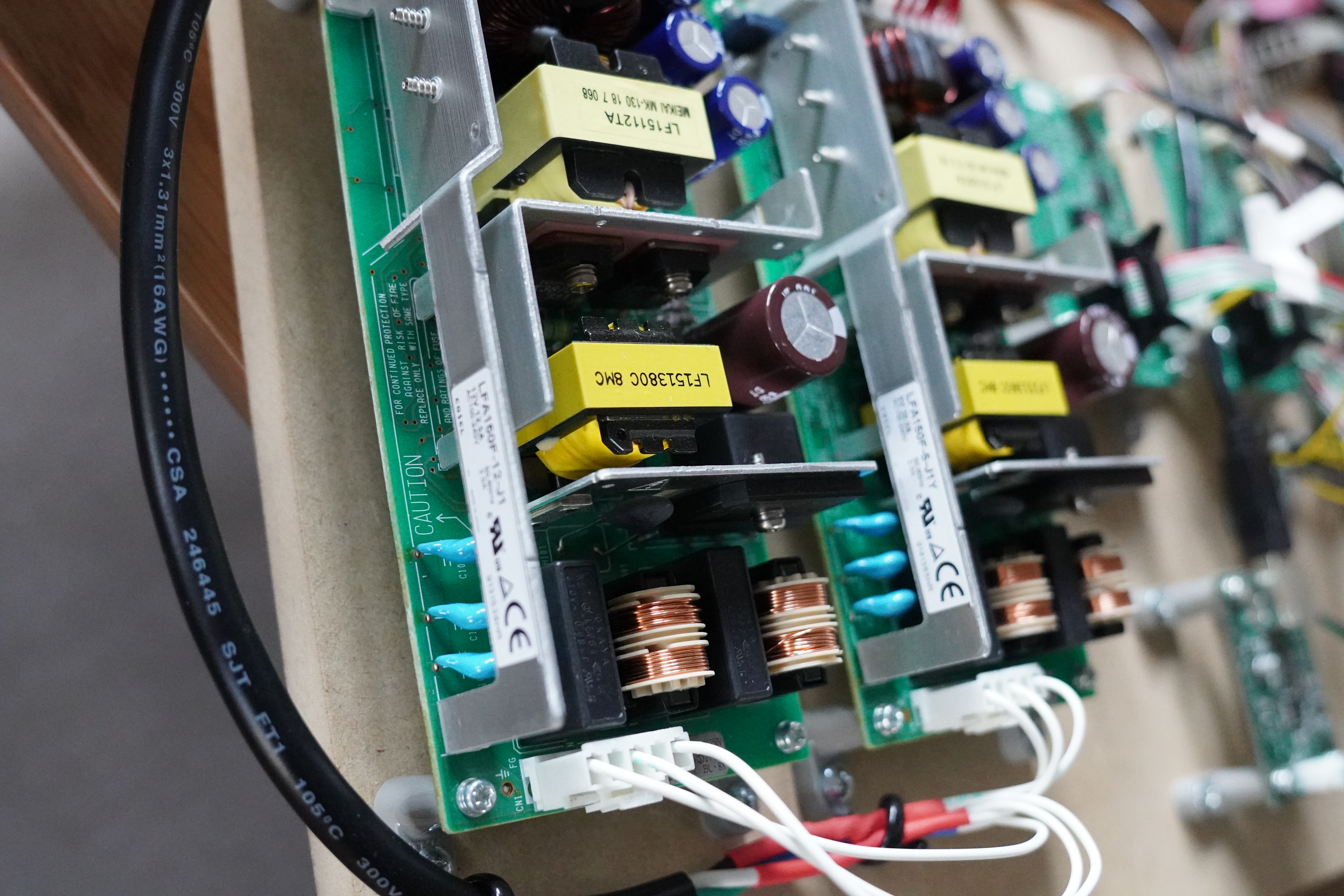
These two units supply all the power needed for the PCB components (sound system, LEDs, touch controller etc). My photos will look a little different at the bottom as we had to jerry rig an extension cable to feed power into the unit since I don't have the original cabling for it. Works fine on American power, there are also reports of it working fine in Europe.
R1 uses a 300VA but that's probably overkill.
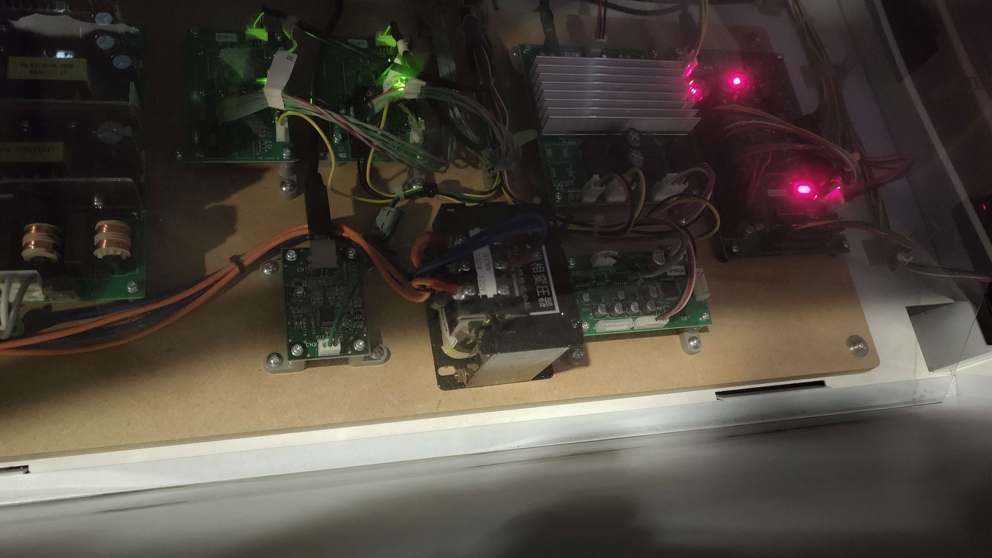
Hits about 200W during attract mode. TODO: power info during songlist pull etc.
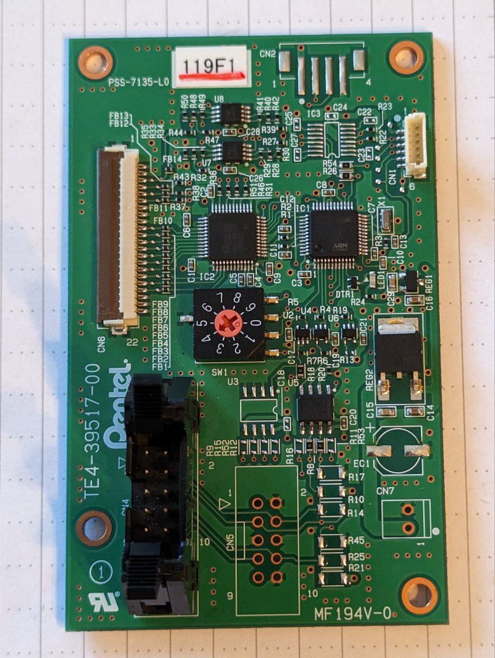
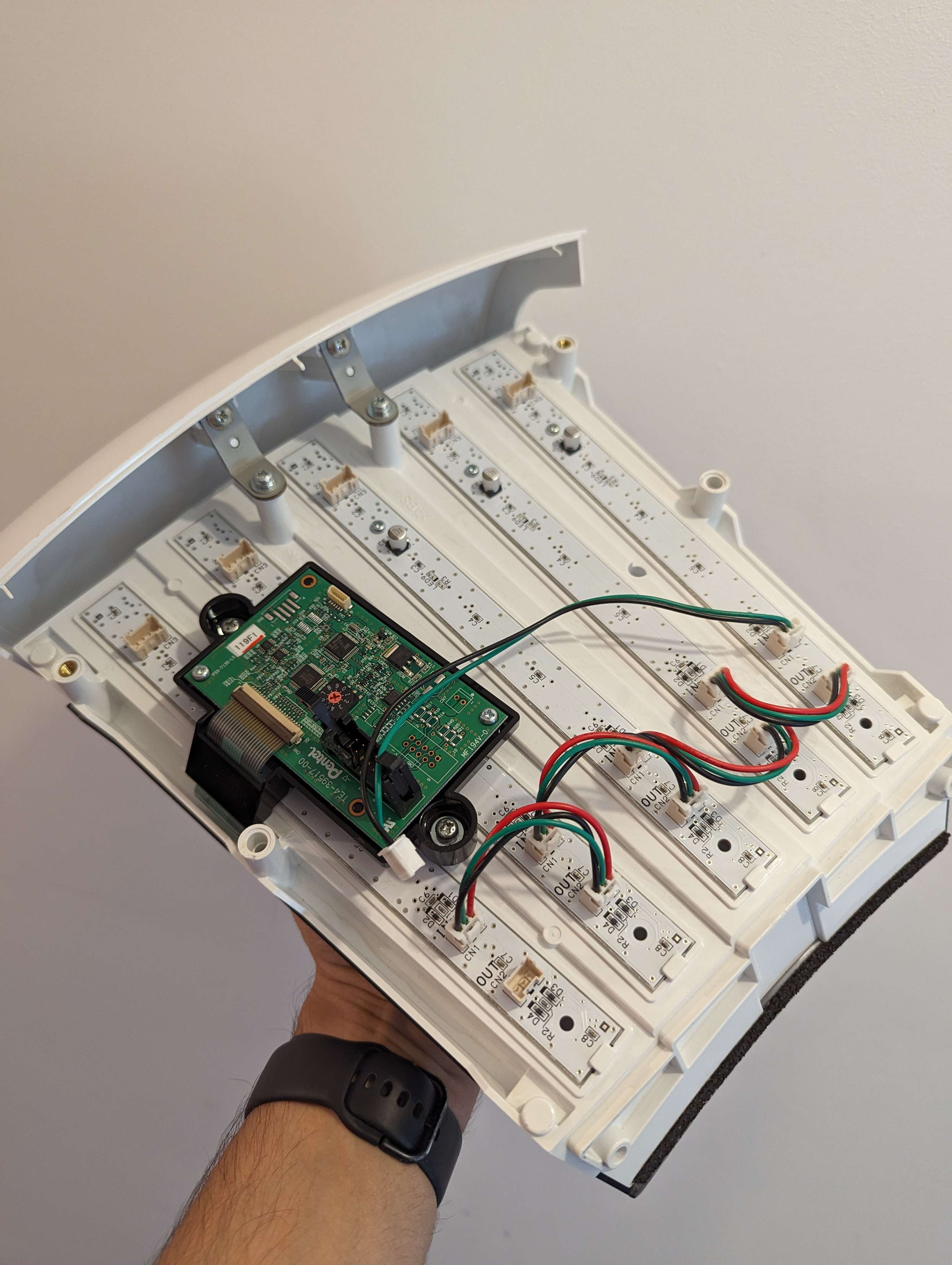
Touch Boards
There are two of these and they each process 6 segments. Together they control the two halves of the touch controller assembly (for a total of 12 segments).
")
Each segment of the touch controller is connected to the others with the help of RS485 through a ribbon cable. The PCBs present on each segment are the exact same with the addition of a custom Pentel IC and some extra components needed to drive the tactile sensor array.

Here's a detailed component list of those boards :
| Component | Reference | Comment |
|---|---|---|
| IC1 | FM3 MB9BF124K | For pinouts see page 12 (LQFP-48) |
| IC2 | Pentel PAC-0815A | Custom capacitive touch controller made for WACCA by Pentel of Japan. |
| IC3 | ADM 3101E | ±15 kV ESD Protected, 3.3 V Single-Channel RS-232 Line Driver/Receiver |
| U5 | 7Lb176 (8BM AHP1) | Differential Bus Tranceiver |
| U7 / U8 | AD8616 | Analog Op Amps |
| CN4 | Hirose HIF3BA | Used to connect all boards to each other using a ribbon |
| CN6 | 22 pin 1mm pitch FFC/FPC Connector | Generic part |
| SW1 | 9 Way binary coded rotary switch | Generic part |
| RG1 | XC6206 662K 3.3V 0.5A Voltage regulator | 3.3V 0.5A Voltage regulator |
| RG2 | 178M05 91 03 | 5V 0.5A Fixed Voltage regulator |
Click to show a Top View picture of the PCB
LED Control Board
It sends the pretty colors to the touch controller.

Here's a rundown of what this board is made out of:
| Component | Reference | Comment |
|---|---|---|
| IC1 | FT232HL FTDI | Single Channel HiSpeed USB to Multipurpose UART/FIFO IC |
| IC2 | 93LC56B | EEPROM for USB descriptor and VID/PID, 6 pin variant |
| IC3 | SN74AHCT1G86 | Single 2-Input XOR Gate |
IC3 Additional info:
Pin 1 - MOSI from FT232HL (Pin 14)
Pin 2 - Trace runs to one pad of R10, through R11 (10k ohm resistor), to ground
Pin 3 - Ground
Pin 4 - LED data out into R12 (100 ohm resistor) to CN2 (LED Data/Ground out)
Pin 5 - 5V, VCC in
2.1ch Amp
, Handles analog sound routing to subwoofer and tweeters") Handles analog sound routing to subwoofer and tweeters
Handles analog sound routing to subwoofer and tweeters
Headphone Amp
, Handles audio output to the control panel") Handles audio output to the control panel
Handles audio output to the control panel
I/O Control Board (837-15257-01)
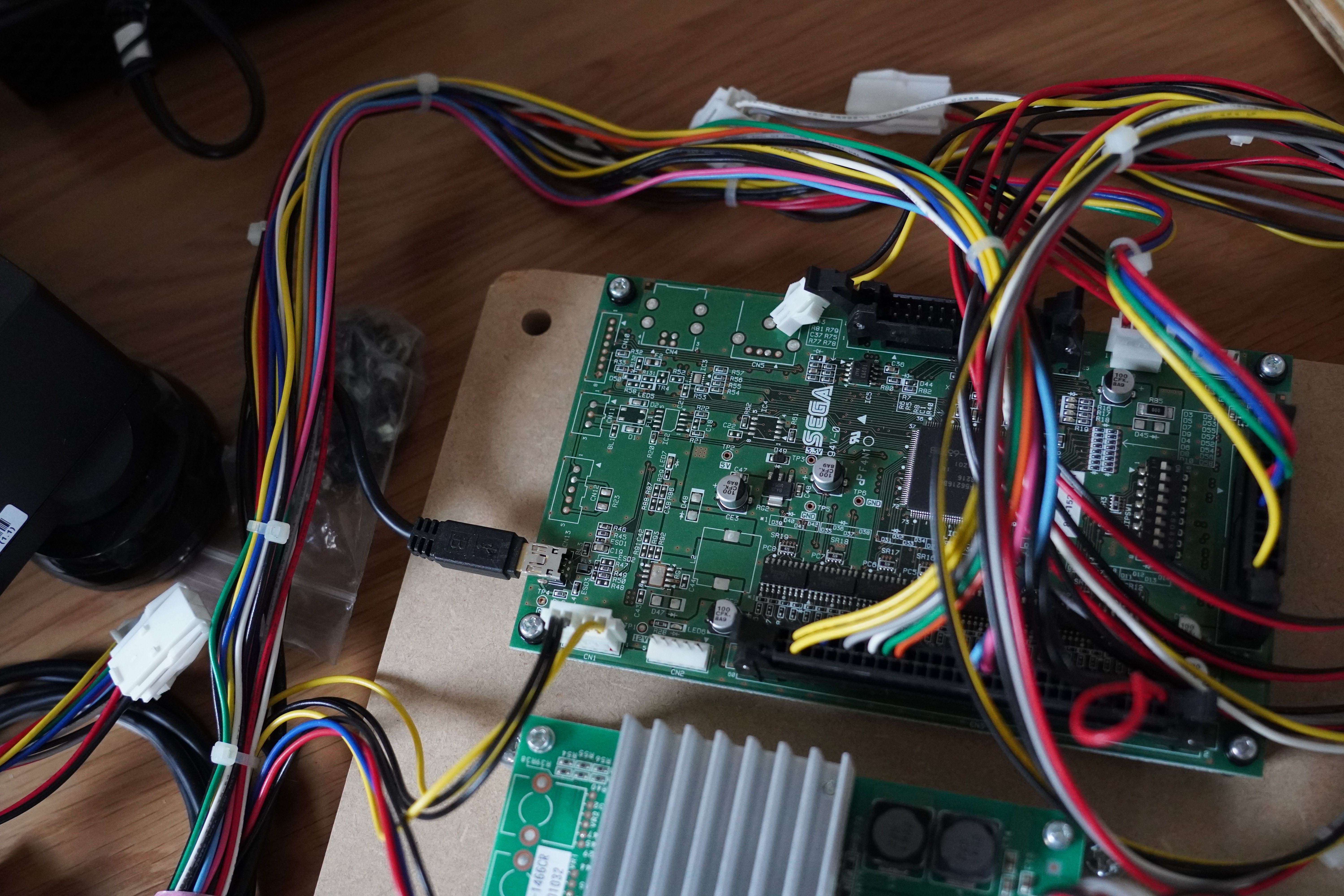 The existence of this board is a bit overkill for what it's used for, likely it had to be used due to SEGA producing the cabinets for Marvelous. This is a newer version of the control board that has a USB port on it, almost all sega cabs use this now.
Note: WACCA does NOT check for a coin counter, so the resistor trick is not needed to apply credits in game.
Control Panel
This giant metal LED lined panel has [4] plugs that connect to
- Card reader
- VFD display to show IC readout for cash cards. Mine had some burn in. Unused.
- Headphone amp jack with VOL UP and VOL DOWN buttons
- All the LEDs
The coin entry stuff connected to the cash box is here too.
Card Reader
The Aime card reader is model number 610-0955. There are lots of good solutions to DIY one of these.
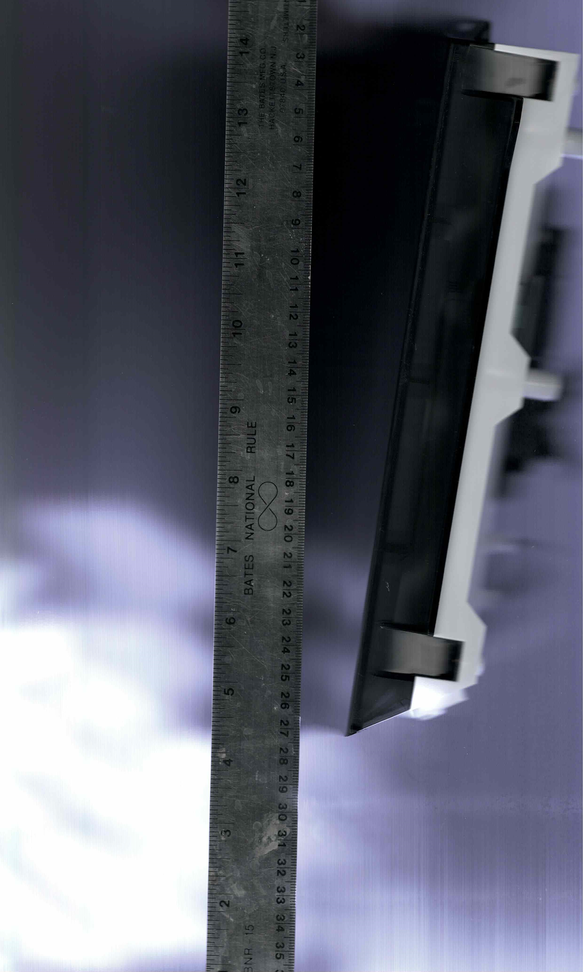
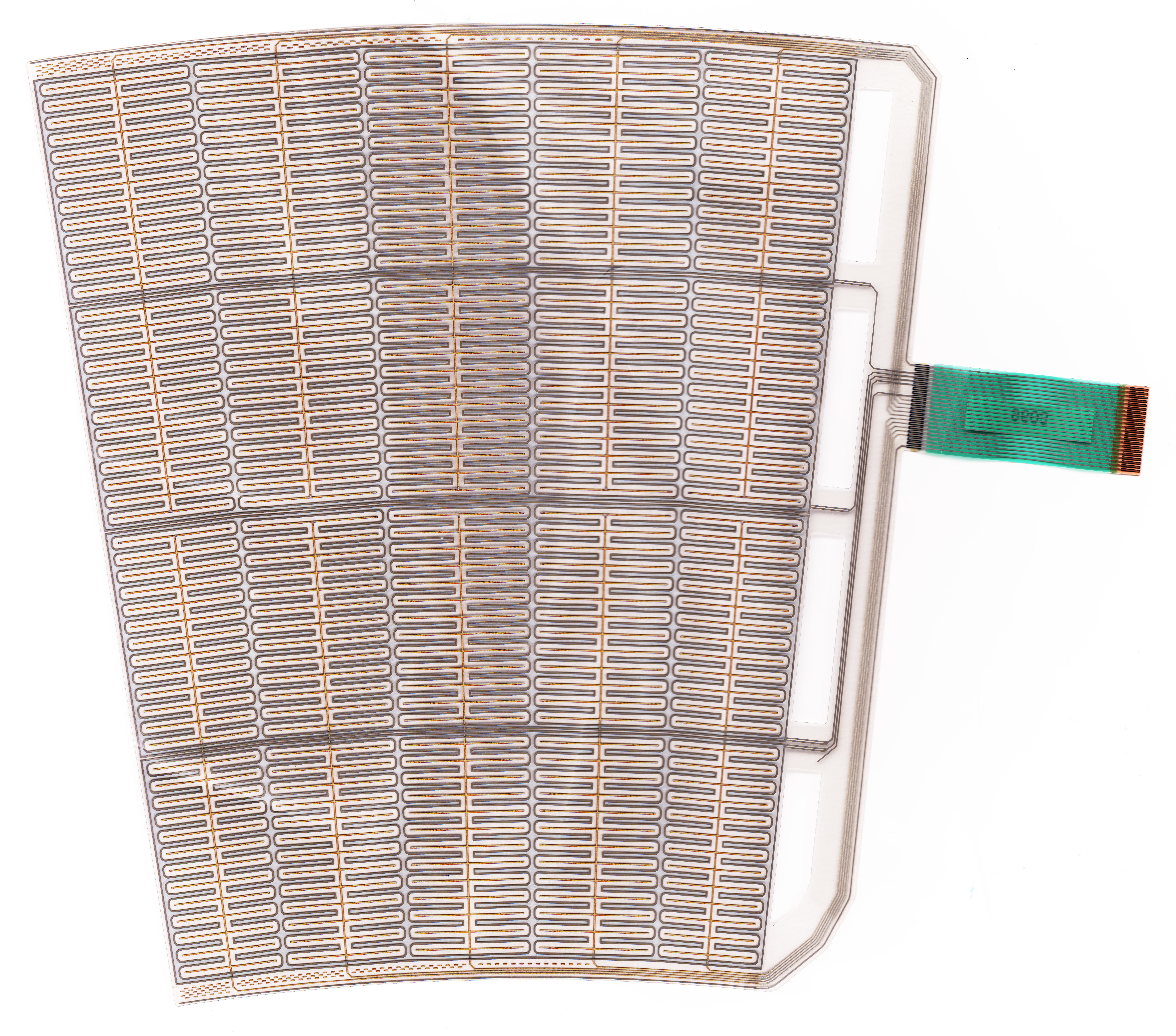
Touch Panels
The touch controller assembly is composed of 12 segments divided into two halves (6 per side, each having their own main controller board). They each have an individual channel ranging from 1 to 6.

Each one of these weighs 1kg (2.2LBS) (870g if the metal bracket is removed) which totals to about 12kg (26LBS).
Each unit has 5 LED strips (each strip has 8 LEDs making for a total of 40 LEDs per segment). In total, there are 480 LEDs in the touch controller assembly
The sensor array is made out of 5 columns and 4 rows amounting to 20 touch zones par segment.
All 12 segments amount to a total of 240 touch zones.
 Click here to download a higher resolution image.
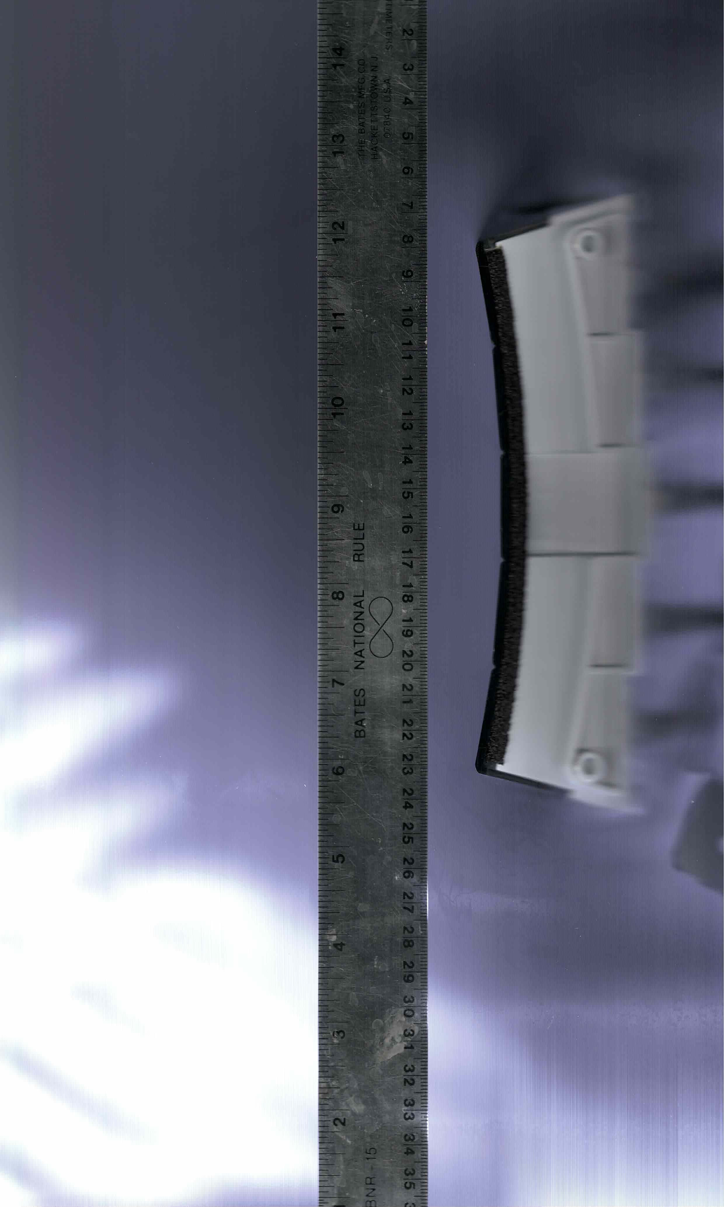
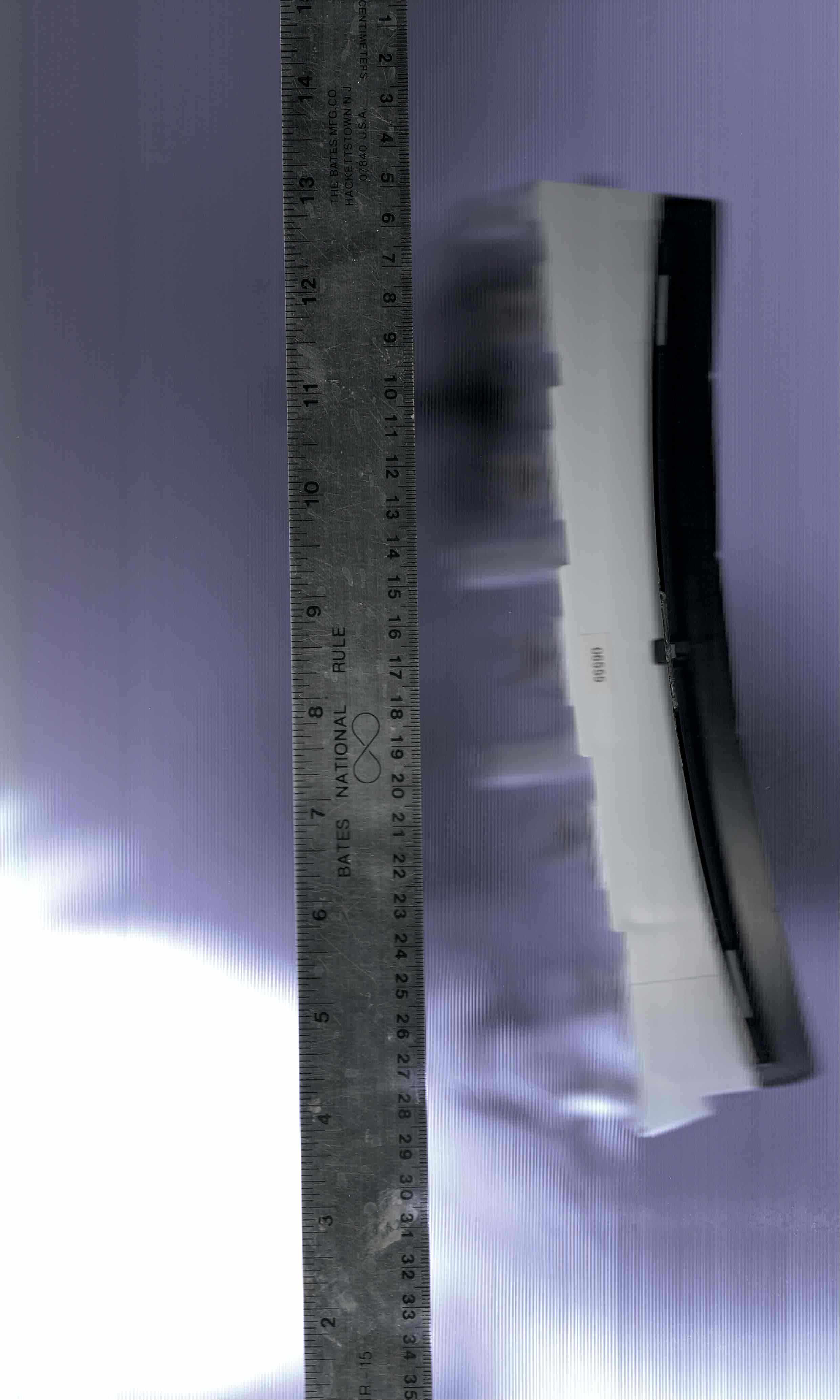
Somehow I never really understood how MASSIVE these units are until I held an individual segment in my hand.
Here are some scans of a segment that shows the curve profile.